# 
[](https://github.com/proddy/EMS-ESP/blob/master/CHANGELOG.md)
[](https://github.com/proddy/EMS-ESP/commits/master)
[](LICENSE)
[](https://travis-ci.com/proddy/EMS-ESP)
[](https://app.codacy.com/app/proddy/EMS-ESP?utm_source=github.com&utm_medium=referral&utm_content=proddy/EMS-ESP&utm_campaign=Badge_Grade_Settings)
[](https://github.com/proddy/EMS-ESP/releases)
[](https://gitter.im/EMS-ESP/community)
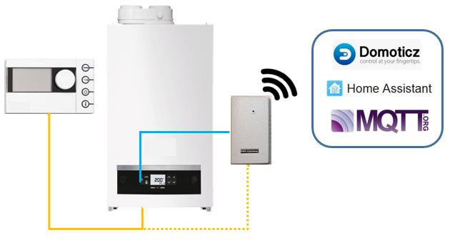
EMS-ESP is a open-source firmware for the Espressif ESP8266 microcontroller that can communicate with **EMS** (Energy Management System) based boilers, thermostats and other modules from manufacturers like Bosch, Buderus, Nefit, Junkers, Worcester and Sieger.
EMS-ESP is the software. It still requires a hardware circuit that can convert the EMS data into Serial data. These can be purchased via https://bbqkees-electronics.nl/.
 ---
## **New Features in version 2**
- Supporting both ESP8266 and ESP32 microcontrollers
- A new multi-user Web interface (based on React/TypeScript)
- A new Console, accessible via Serial and Telnet
- Tighter security in both Web and Console. Admin privileges required to access core settings and commands.
- Support for Home Assistant MQTT Discovery (https://www.home-assistant.io/docs/mqtt/discovery/)
- Can be run standalone as an independent Access Point or join an existing WiFi network
- Easier first-time configuration via a web Captive Portal
- Supporting over 70 EMS devices (boilers, thermostats, solar modules, mixing modules, heat pumps, gateways)
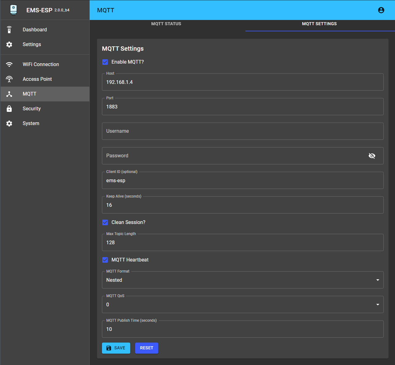
## **Screenshots**
| | |
| --- | --- |
|
---
## **New Features in version 2**
- Supporting both ESP8266 and ESP32 microcontrollers
- A new multi-user Web interface (based on React/TypeScript)
- A new Console, accessible via Serial and Telnet
- Tighter security in both Web and Console. Admin privileges required to access core settings and commands.
- Support for Home Assistant MQTT Discovery (https://www.home-assistant.io/docs/mqtt/discovery/)
- Can be run standalone as an independent Access Point or join an existing WiFi network
- Easier first-time configuration via a web Captive Portal
- Supporting over 70 EMS devices (boilers, thermostats, solar modules, mixing modules, heat pumps, gateways)
## **Screenshots**
| | |
| --- | --- |
|  |
|  |
|
|
|  |
|  |
|
 ## **Migrating from version 1.9**
EMS-ESP will attempt to automatically migrate the 1.9 settings.
Note there are some noticeable differences to be aware of in version 2:
- MQTT base has been removed. All MQTT topics are prefixed with only the hostname, for example `ems-esp/status` as opposed to `home/ems-esp/status`.
- There is no "serial mode" anymore like with version 1.9. When the Wifi cannot connect to the SSID it will automatically enter a "safe" mode where the Serial console is activated (note Serial is always available on the ESP32 because it has multiple UARTs). The EMS-ESP's LED will blink fast when in Serial mode. When this happens connect via a USB using baud 115200.
If you run into issues try first erasing the ESP8266 with `esptool.py erase_flash` and uploading the new firmware manually. BBQKees has a good write-up at https://bbqkees-electronics.nl/wiki/gateway/firmware-update-to-v2.html.
## **Building the firmware with PlatformIO**
1. Install [PlatformIO](https://platformio.org/install) and [NodeJS](https://nodejs.org/en/).
2. Decide how you want to upload the firmware, via USB or OTA (Over The Air). OTA requires that a version of EMS-ESP is already running.
3. Create a new file called `pio_local.ini` and add these two lines for USB:
```yaml
upload_protocol = esptool
upload_port =
```
or these 2 for OTA:
```yaml
upload_protocol = espota
upload_flags =
--port=8266
--auth=ems-esp-neo
upload_port = ems-esp.local
```
3. type `pio run -t upload` to build and upload the firmware
## **Uploading the firmware**
Here we'll use the command-line. You'll need [Python]( https://www.python.org/downloads/) (version 3) installed and these 2 scripts:
- `esptool.py`. Install using `pip install esptool`.
- `espota.py` downloaded from https://github.com/esp8266/Arduino/blob/master/tools/espota.py
Both these tools are also in the repo in the `scripts` directory.
Next step is to fetch the latest firmware binary from https://github.com/proddy/EMS-ESP/releases, and if you're using USB with an ESP8266:
`esptool.py -p -b 921600 write_flash 0x00000 `
and for OTA:
`espota.py --debug --progress --port 8266 --auth ems-esp-neo -i -f `
## **Setting EMS-ESP up for the first time**
- After powering up the ESP, watch the onboard blue LED. A solid light means good connection and EMS data is coming in. A slow pulse means either the WiFi or the EMS bus is not connected yet. A very fast pulse is when the system is booting up and configuring itself which typically takes 5 seconds.
- Connect to the Access Point called `ems-esp` using the WPA password `ems-esp-neo`. When you see the captive portal sign-in with username `admin` and password `admin`. Set the WiFi credentials and go back to http://ems-esp. Remember to change the passwords!
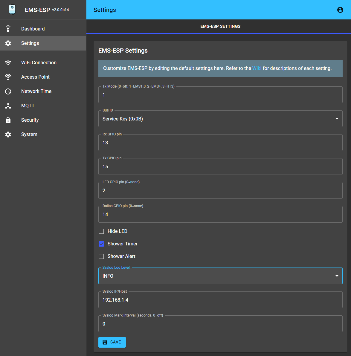
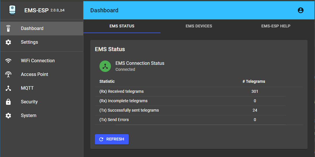
- First thing to check is if Tx is working and that you have a connection to the EMS bus. If Tx fails are shown in the Web interface try changing the Tx Mode from the settings page. There is no need to re-start the EMS-ESP.
- If Rx incomplete telegrams are reported in the Web interface, don't panic. Some telegrams can be missed and this is usually caused by noise interference on the line.
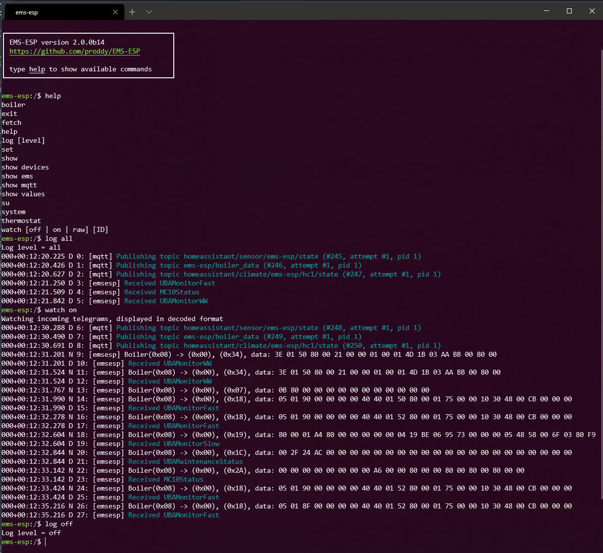
## **Using the Console**
Connecting to the console will give you more insight into the EMS bus traffic, MQTT queues and the full device information.
The console is reachable via Telnet (port 22) or via the Serial port if using an USB (on baud 115200). To change any settings in the console you must be admin (use `su` with the default password `ems-esp-neo`).
Some of the most common commands are:
* `help` lists the commands and keywords. This works in each context.
* `exit` will exit the console or exit the current context. `CTRL-D` does the same.
* `CTRL-U` for Undo
* `` for auto-complete
* Some specific commands are behind contexts. Think of this as a sub-menu. e.g. `system`, `thermostat`. The path will always show you which context you are in. `$` is the root.
* `su` will switch to the Admin super-user. The default password is `ems-esp-neo` and can be changed with `passwd` from the system menu or via the Web interface (called secret password). When in Admin mode the command prompt switches from `$` to `#`.
* Some settings can be changed in the console. The `set` command will list them.
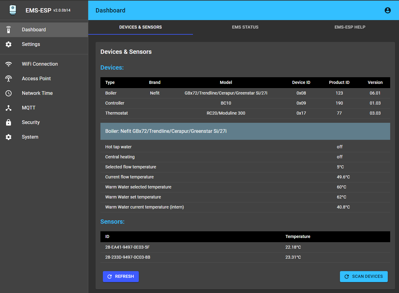
* `show` shows the data specific to the which context you're in. From the root it will show you all the EMS device information and any external temperature sensors.
* `log` sets the logging level. `log off` disables logging. Use `log debug` for debugging commands and actions. This will be reset next time the console is opened.
* `watch` will output the incoming Rx telegrams directly to the console. You can also put on a watch on a specific EMS device ID or telegram ID. Also choose to output as verbose text as raw data bytes.
The `call` command is to execute a command. The command names (`[cmd]`) are the same as the MQTT commands listed in the MQTT section.
```
(* = available in su/Admin mode)
common commands available in all contexts:
exit
help
log [level]
watch [ID]
su
(from the root)
system (enters a context)
boiler (enters a context)
thermostat (enters a context)
set
fetch
scan devices [deep] *
send telegram <"XX XX ..."> *
set bus_id *
set tx_mode *
show
show devices
show ems
show values
show mqtt
system
set
show
format *
show users *
passwd *
restart *
set wifi hostname *
set wifi password *
set wifi ssid *
wifi reconnect *
pin [data] *
boiler
read *
call [cmd] [data] *
thermostat
set
set master [device ID] *
read *
call [cmd] [data] [heating circuit] *
```
----------
## **MQTT commands**
All commands must be written as `{"cmd": ,"data":, "id":}`.
The `id` can be replaced with `hc` for some devices that use heating circuits, and represented either as a string or a number. `cmd` is a string, `data` can be a string or number.
topic = *boiler_cmd*
```
comfort
flowtemp
wwtemp
boilhyston (negative value)
boilhystoff (positive value)
burnperiod
burnminpower <%>
burnmaxpower <%>
pumpdelay
```
topic = *thermostat_cmd*
```
--- without hc ---
wwmode
calinttemp
minexttemp
building
language (0=de, 1=nl, 2=fr, 3=it) only RC30
display (0=int temp, 1= int set, 2=ext. temp, 3=burner, 4=ww, 5=mode, 6=time, 7=date, 8=smoke) only RC30
clockoffset (only RC30)
--- with hc ---
mode
temp
nighttemp
daytemp
nofrosttemp
ecotemp
heattemp
summertemp
designtemp
offsettemp
holidaytemp
remotetemp
control <0 | 1 | 2>
pause
party
holiday
date
```
topic = *system_cmd*
```
send <"0B XX XX ..">
pin
```
## **Migrating from version 1.9**
EMS-ESP will attempt to automatically migrate the 1.9 settings.
Note there are some noticeable differences to be aware of in version 2:
- MQTT base has been removed. All MQTT topics are prefixed with only the hostname, for example `ems-esp/status` as opposed to `home/ems-esp/status`.
- There is no "serial mode" anymore like with version 1.9. When the Wifi cannot connect to the SSID it will automatically enter a "safe" mode where the Serial console is activated (note Serial is always available on the ESP32 because it has multiple UARTs). The EMS-ESP's LED will blink fast when in Serial mode. When this happens connect via a USB using baud 115200.
If you run into issues try first erasing the ESP8266 with `esptool.py erase_flash` and uploading the new firmware manually. BBQKees has a good write-up at https://bbqkees-electronics.nl/wiki/gateway/firmware-update-to-v2.html.
## **Building the firmware with PlatformIO**
1. Install [PlatformIO](https://platformio.org/install) and [NodeJS](https://nodejs.org/en/).
2. Decide how you want to upload the firmware, via USB or OTA (Over The Air). OTA requires that a version of EMS-ESP is already running.
3. Create a new file called `pio_local.ini` and add these two lines for USB:
```yaml
upload_protocol = esptool
upload_port =
```
or these 2 for OTA:
```yaml
upload_protocol = espota
upload_flags =
--port=8266
--auth=ems-esp-neo
upload_port = ems-esp.local
```
3. type `pio run -t upload` to build and upload the firmware
## **Uploading the firmware**
Here we'll use the command-line. You'll need [Python]( https://www.python.org/downloads/) (version 3) installed and these 2 scripts:
- `esptool.py`. Install using `pip install esptool`.
- `espota.py` downloaded from https://github.com/esp8266/Arduino/blob/master/tools/espota.py
Both these tools are also in the repo in the `scripts` directory.
Next step is to fetch the latest firmware binary from https://github.com/proddy/EMS-ESP/releases, and if you're using USB with an ESP8266:
`esptool.py -p -b 921600 write_flash 0x00000 `
and for OTA:
`espota.py --debug --progress --port 8266 --auth ems-esp-neo -i -f `
## **Setting EMS-ESP up for the first time**
- After powering up the ESP, watch the onboard blue LED. A solid light means good connection and EMS data is coming in. A slow pulse means either the WiFi or the EMS bus is not connected yet. A very fast pulse is when the system is booting up and configuring itself which typically takes 5 seconds.
- Connect to the Access Point called `ems-esp` using the WPA password `ems-esp-neo`. When you see the captive portal sign-in with username `admin` and password `admin`. Set the WiFi credentials and go back to http://ems-esp. Remember to change the passwords!
- First thing to check is if Tx is working and that you have a connection to the EMS bus. If Tx fails are shown in the Web interface try changing the Tx Mode from the settings page. There is no need to re-start the EMS-ESP.
- If Rx incomplete telegrams are reported in the Web interface, don't panic. Some telegrams can be missed and this is usually caused by noise interference on the line.
## **Using the Console**
Connecting to the console will give you more insight into the EMS bus traffic, MQTT queues and the full device information.
The console is reachable via Telnet (port 22) or via the Serial port if using an USB (on baud 115200). To change any settings in the console you must be admin (use `su` with the default password `ems-esp-neo`).
Some of the most common commands are:
* `help` lists the commands and keywords. This works in each context.
* `exit` will exit the console or exit the current context. `CTRL-D` does the same.
* `CTRL-U` for Undo
* `` for auto-complete
* Some specific commands are behind contexts. Think of this as a sub-menu. e.g. `system`, `thermostat`. The path will always show you which context you are in. `$` is the root.
* `su` will switch to the Admin super-user. The default password is `ems-esp-neo` and can be changed with `passwd` from the system menu or via the Web interface (called secret password). When in Admin mode the command prompt switches from `$` to `#`.
* Some settings can be changed in the console. The `set` command will list them.
* `show` shows the data specific to the which context you're in. From the root it will show you all the EMS device information and any external temperature sensors.
* `log` sets the logging level. `log off` disables logging. Use `log debug` for debugging commands and actions. This will be reset next time the console is opened.
* `watch` will output the incoming Rx telegrams directly to the console. You can also put on a watch on a specific EMS device ID or telegram ID. Also choose to output as verbose text as raw data bytes.
The `call` command is to execute a command. The command names (`[cmd]`) are the same as the MQTT commands listed in the MQTT section.
```
(* = available in su/Admin mode)
common commands available in all contexts:
exit
help
log [level]
watch [ID]
su
(from the root)
system (enters a context)
boiler (enters a context)
thermostat (enters a context)
set
fetch
scan devices [deep] *
send telegram <"XX XX ..."> *
set bus_id *
set tx_mode *
show
show devices
show ems
show values
show mqtt
system
set
show
format *
show users *
passwd *
restart *
set wifi hostname *
set wifi password *
set wifi ssid *
wifi reconnect *
pin [data] *
boiler
read *
call [cmd] [data] *
thermostat
set
set master [device ID] *
read *
call [cmd] [data] [heating circuit] *
```
----------
## **MQTT commands**
All commands must be written as `{"cmd": ,"data":, "id":}`.
The `id` can be replaced with `hc` for some devices that use heating circuits, and represented either as a string or a number. `cmd` is a string, `data` can be a string or number.
topic = *boiler_cmd*
```
comfort
flowtemp
wwtemp
boilhyston (negative value)
boilhystoff (positive value)
burnperiod
burnminpower <%>
burnmaxpower <%>
pumpdelay
```
topic = *thermostat_cmd*
```
--- without hc ---
wwmode
calinttemp
minexttemp
building
language (0=de, 1=nl, 2=fr, 3=it) only RC30
display (0=int temp, 1= int set, 2=ext. temp, 3=burner, 4=ww, 5=mode, 6=time, 7=date, 8=smoke) only RC30
clockoffset (only RC30)
--- with hc ---
mode
temp
nighttemp
daytemp
nofrosttemp
ecotemp
heattemp
summertemp
designtemp
offsettemp
holidaytemp
remotetemp
control <0 | 1 | 2>
pause
party
holiday
date
```
topic = *system_cmd*
```
send <"0B XX XX ..">
pin
```